Modifying a Speaker Protection Board
This article is based on the author's own research and testing and does not guarantee the accuracy or completeness of the information provided.
If you use the information in this article, you do so at your own risk. The author assumes no responsibility for any issues or damages resulting from its use.
AliExpress Link
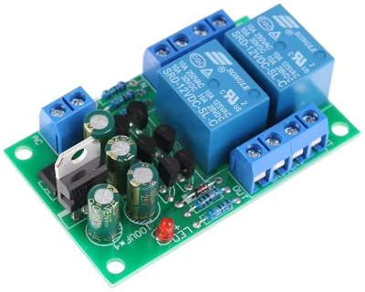
High Quality 1PC Audio Speaker Protection Board Boot Delay DC Protect Kit DIY Double Channel
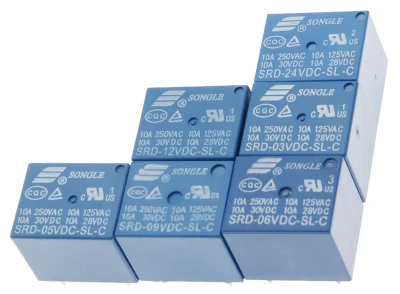
Relay SRD-05VDC-SL-C SRD-24VDC-SL-C SRD-12VDC-SL-C SRD-12VDC-SL-A 3V 5V 12V 24V 48V 10A 250VAC 5PIN 4PIN Relays Relais
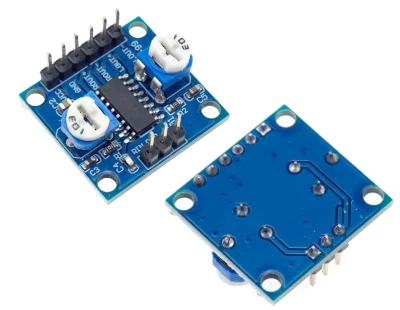
1-5Pcs PAM8406 Digital Amplifier Board With Volume Potentiometer 5Wx2 Stereo M70
BTL warning. It is recommended to remove the trimmer potentiometer and replace it with a good-quality dual-gang volume control.
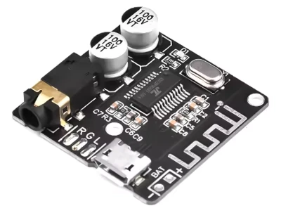
1-10PCS DIY Bluetooth Audio Receiver Board Bluetooth 5.0 MP3 Lossless Car Audio Decoder Board Wireless Stereo Music Module XY-BT
There are also v4.1 versions for sale, so check the supported Bluetooth version carefully.
Speaker Protection Board
While browsing AliExpress, I found something called an audio speaker protection board, so I decided to give it a try.
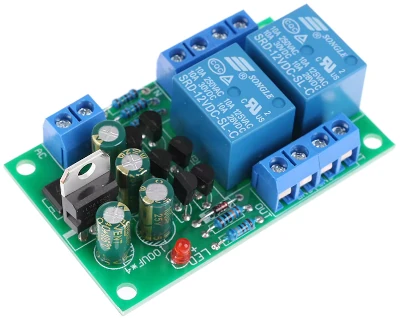
This one is rated for AC 12-16V. It is sold as a kit rather than assembled (although assembled versions are also available).
There were quite a few similar products, but I chose one with a reasonable number of reviews (see Aliexpress Link).
I bought two, and both arrived safely.
I have a DIY digital amplifier, so I was thinking about incorporating this into it. However, as mentioned above, this board is designed for AC (alternating current) 12V-16V.
I expected that it would not work as-is, so I bought it with the intention of modifying it.
Here is the board.
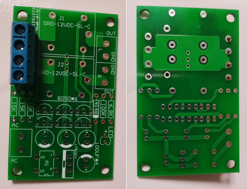
From the board and the photos of the completed product, I was able to determine the following first.
- There is a bridge rectifier to convert the AC input to DC (marked
A1on the board).
Digital amplifiers and similar devices use DC (direct current), so this is not necessary. - There is a three-terminal regulator after the bridge rectifier (marked
L7812CVon the board).
This converts the rectified voltage from AC 12-16V to 12V DC. A digital amplifier that operates at 12V DC or less does not need this either.
※ SinceACV × √2is the theoretical value, AC 12V becomes approximately DC 17V. Due to the voltage drop across the diodes, the actual voltage is around 15V.
Therefore, I expected that the board should work with a DC-powered amplifier if these parts were bypassed.
* It is also possible to input DC 12V before the bridge rectifier. However, due to the voltage drop caused by the bridge rectifier and three-terminal regulator, the voltage supplied to the circuit itself would be around 9V, which would likely cause the relay to operate unreliably.
I also decided to convert it to DC 5V so that I could use it with the PAM8406 I had on hand. This required the following modifications as well.
- Replace the relay
Since the voltage supplied to the circuit will change from DC 12V to DC 5V, the relay needs to be replaced. The board comes with anSRD-12VDC-SL-C, so I replaced it with anSRD-05VDC-SL-C.
I boughtSRD-05VDC-SL-C 5PIN, 5PCS(see Aliexpress Link). - Change the resistor value so that the 5V relay can operate
The circuit will be supplied with DC 5V instead of DC 12V. As can be seen from the product page for the relay above, the required current (coil current) is as follows:- 5V: 72 mA
- 12V: 30 mA
Since the voltage also drops from 12V to 5V, the relay would most likely not respond at all if the resistor were left unchanged.
Modification
First, here is a photo of the board after applying the modifications described above.
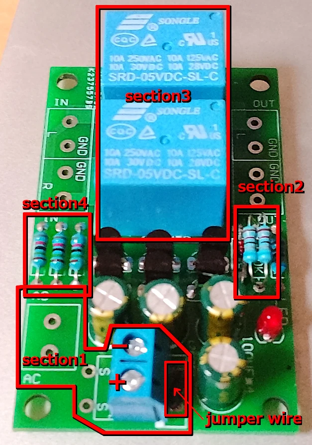
At this point, there are three modification areas (Section 1 - Section 3).
Section 1
- Do not install either
A1orL7812CV. - The terminal that was originally connected to the
ACsection was instead connected to the output side ofA1(where+and-are printed). - As you can see from the PCB traces, this alone would not supply
+to the circuit, so short both ends ofL7812CVwith a jumper wire. Be careful not to touch the center pad and cause a short circuit. I used an insulated wire rather than a cut-off component lead.
With this modification, the DC supplied to the terminal goes directly into the circuit.
Section 2
This is the part mentioned above: changing the resistor value so that the 5V relay can operate. The board originally has a 100K resistor here. When I asked an AI about this, it told me that "shorting this part will make the relay respond," but that will kill the transistor, so don't do that lol.
Section 3
Replace the relay from SRD-12VDC-SL-C with SRD-05VDC-SL-C.
Section 4
I had not noticed this at this point. (Described later.)
Testing
I have a modified USB cable made from a USB cable I bought at a 100-yen shop (one that had already suffered a broken wire or something), so I connected it to the terminal and then to a mobile battery for testing.
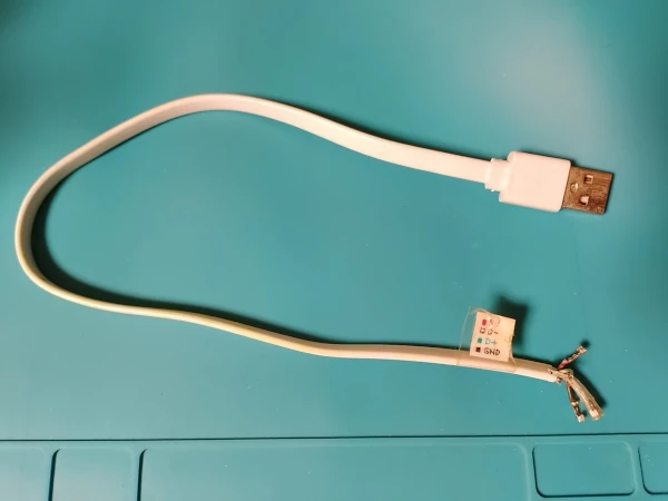
At this point, I tried the following for Section 2.
- First, I tested it with 10K.
The relay operated with a "click" in less than one second. - I changed it to 47K.
It sometimes operated, but it was unstable. The delay increased to a little over two seconds. - I wanted to use 33K, but I did not have one, so I connected two 68K resistors in parallel (= 34K).
The delay was a little over one second, and the operation was stable, so I settled on this.
I confirmed that the relay responds with a DC 5V input.
Connecting the amplifier
I connected the PAM8406 and checked whether it would actually work.
Looking at the traces on the back of this board makes it immediately obvious, but the speaker GND is shared.
Many digital amplifiers, including the PAM8406, use a BTL connection. Unlike a single-ended amplifier, L-/R- (which have a voltage in the opposite phase to the + output) are not GND. They must not be shorted together.
Connecting the negative outputs from the amplifier (L-/R-) to this board can, in the worst case, destroy the amplifier, so absolutely do not connect them.
So what should you do?
- Connect L+/R+ to L/R on this board (the side that is not shorted together on the back of the board).
- Connect L-/R- directly to the speakers without passing them through this board.
I connected the PAM8406 while paying attention to the short-circuit issue described above, but, as it turned out, it did not work at all lol.
In fact, this board is not just a delay relay. As the "DC protection" in the product description indicates (something I noticed again later lol), it also detects DC flowing to the speakers and prevents the relay from operating when DC leakage is detected.
For such an inexpensive circuit, it was actually quite well designed.
The PCB traces already show that it is not designed for BTL operation = it is intended for single-ended amplifiers. In that case, the DC protection does not cause any problems. With BTL, however, voltage is applied to both the + and - outputs, so the DC protection was triggered and the relay would not turn on. That was the reason it did not work.
* With VDD = 5V, both OUT+ and OUT- have approximately 2.5V (slightly less) of DC voltage even when there is no signal.
One possible approach would be to change the resistor connected to the DC protection circuit (Section 4) so that the DC protection does not activate even when the PAM8406 produces 2.5V. However, that seemed like a hassle (and, after all, I bought this board because I wanted a delay relay to prevent pop noise), so I dealt with it by removing the resistor in Section 4.
The DC protection will no longer work, but if preventing pop noise at startup is sufficient for your requirements, this modification does the job.
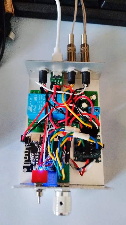
In the end, the amplifier became something like this:
- PAM8406
- Bluetooth (v5) support
Compatible boards are available cheaply. - The speaker protection board used in this modification
All of the above are supplied with 5V from a USB-C connector (split in parallel). - Two audio inputs: a 3.5mm stereo phone jack and Bluetooth
They are switched using a 2-circuit, 2-position toggle switch. (The GND of the audio input does not need to be switched and can be shared.) - The speakers are also connected using a 3.5mm phone jack.
I used a Takachi YM-10 (YM10-3-7) aluminum enclosure to keep the unit compact, so a speaker terminal would have been difficult to fit. I am also using the YM series in a somewhat unusual way, rather than its typical use with the silver side as the front.
Originally, my child had an AG03, but there was no way to drive the passive speakers I had on hand, so I made this amplifier.
Bluetooth was not a requirement, but considering that it might also be used as a standalone amplifier, being able to play audio from a smartphone or similar device via Bluetooth makes it more versatile.
Here is a photo. I used YAMORI GRIP (extra-strong double-sided gel tape), which can be bought at 100-yen shops and elsewhere, to secure the boards. I protected the terminals with masking tape so that they would not touch the case.
* YAMORI GRIP itself is quite thick (2 mm), so that alone is probably enough in many cases. However, when using a metal case, I think it is better to take some precautions just in case.
Other Digital Amplifiers
I also have a TA2020 (based on an NFJ board), so I will probably make a version that keeps the DC 12V supply at some point.
In that case, only Section 1 and Section 4 need to be modified.
There are also other digital amplifiers such as the PAM8403, which is said to have more noticeable pop noise than the PAM8406. Therefore, if you want to reduce pop noise on a digital amplifier at relatively low cost, the modifications described in this article may also be useful.
Since this involves modifying electronic hardware, please try it at your own risk.